Dimensions (Width × Height, unit: mm):
(1) Height 50 Series: 100×50, 150×50, 200×50, 300×50, 400×50
(2) Height 100 Series: 100×100, 150×100, 200×100, 300×100, 400×100, 500×100, 600×100, 800×100
(3) Height 150 Series: 200×150, 300×150, 400×150, 500×150, 600×150, 800×150, 1000×150
(4) Height 200 Series: 300×200, 400×200, 500×200, 600×200, 800×200, 1000×200, 1200×200
(5) Extra‑long Span / Special Widened Cable Tray for Power Plants: 1000×100, 1000×150, 1000×200, 1200×200
Plate Thickness (unit: mm): 1.0/1.2/1.5/2.0/2.5/3.0/3.5
Ⅰ. Product Definition:
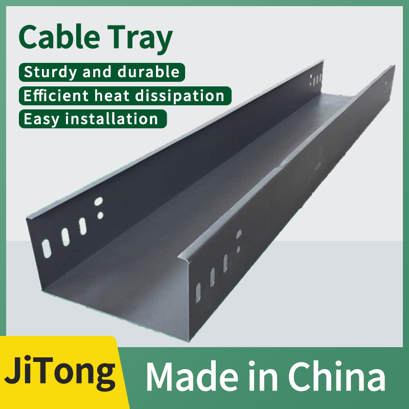
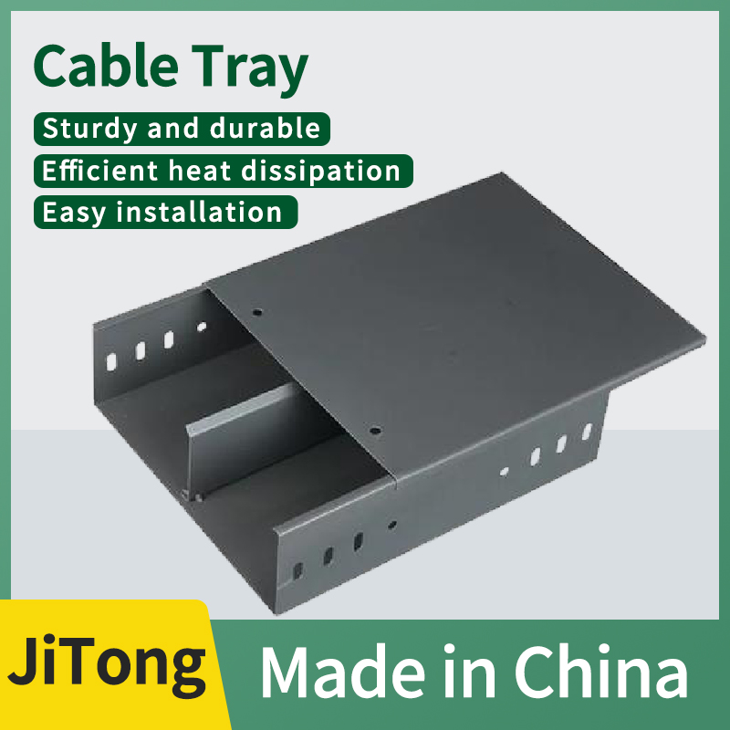
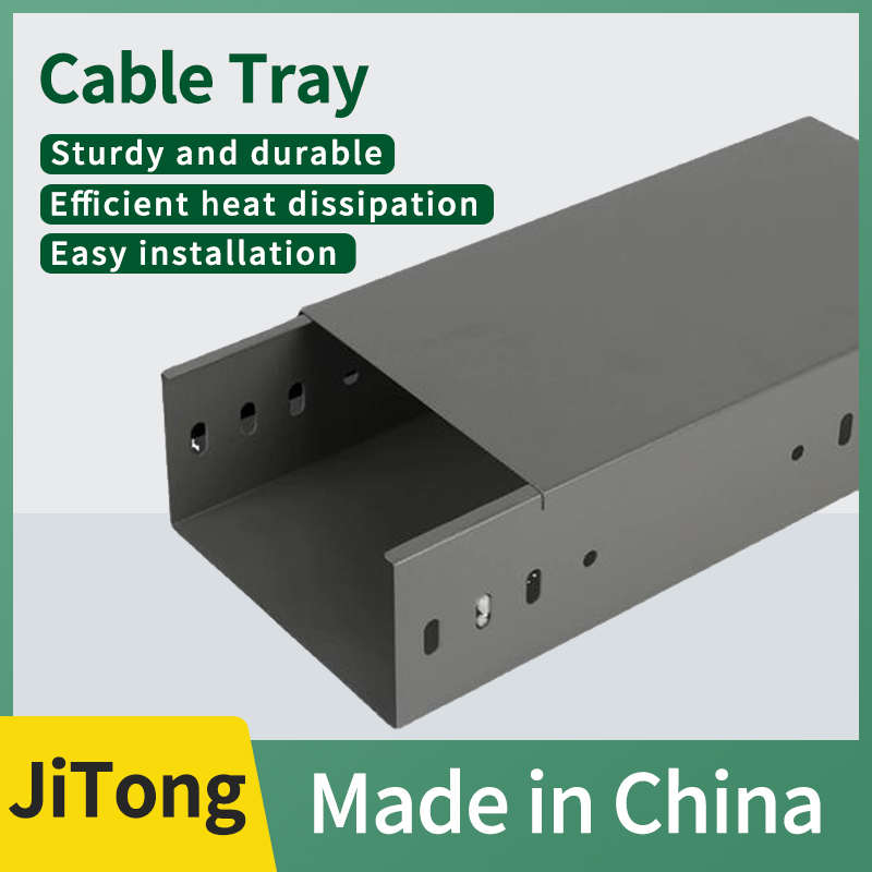
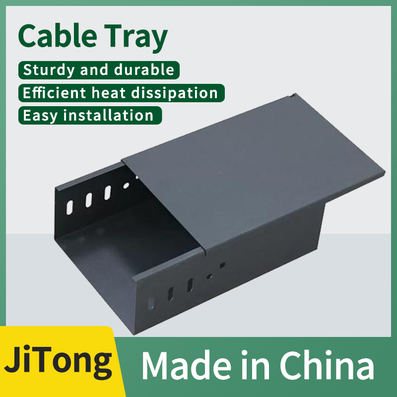
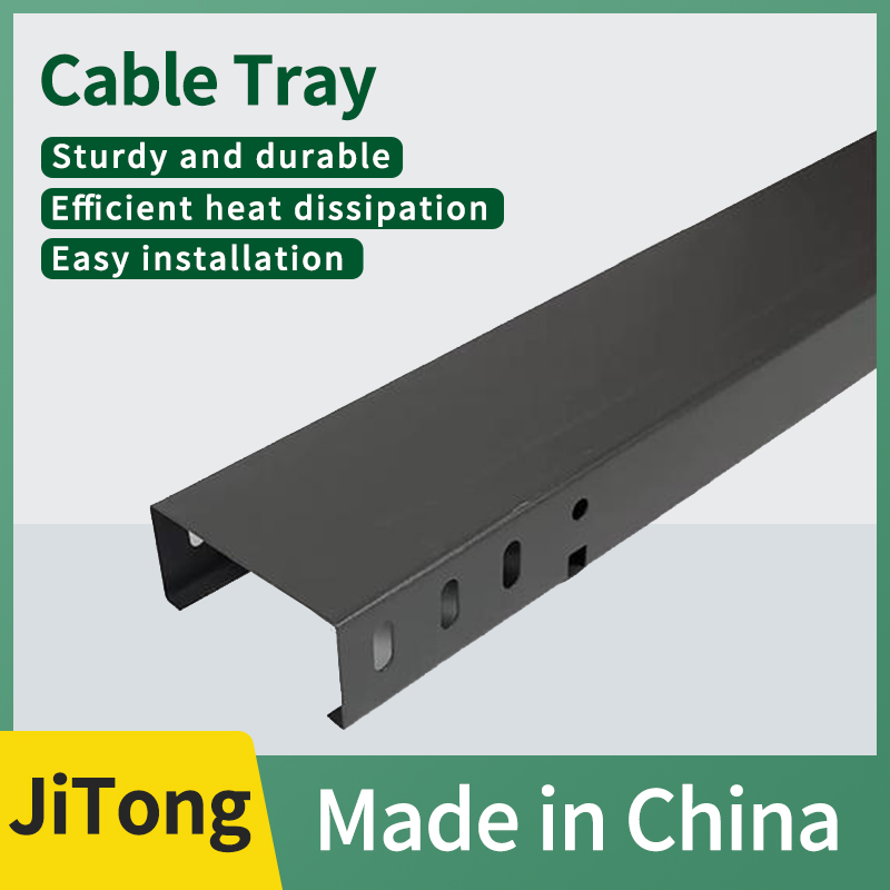
The fire-resistant trough cable tray (fully enclosed fire-resistant trough box) is made of Q235 cold-rolled steel plates bent into a fully enclosed U-shaped trough body, equipped with a fire-resistant cover plate of the same process. The base material is first treated with anti-corrosion primer, and then sprayed with an intumescent fire-resistant coating, or adopts a double-layer fire-resistant and heat-insulating core composite structure. It is specifically designed for laying fire emergency lines, maintaining cable electrification in case of a fire, and blocking the spread of flames and smoke.
Two major mainstream structural types: 1. Coated fire-resistant channel tray. Regular galvanized/hot-dip galvanized channel trays are internally and externally sprayed with a thick layer of intumescent fire-resistant coating, offering a moderate cost and suitable for civil and general industrial use.
2. Double-layer composite fire-resistant cable tray, with aluminum silicate and rock wool fire-resistant insulation layers filled between the double steel plates, boasts a fire resistance limit of up to 90/120 minutes, making it specifically suitable for tunnels, underground utility tunnels, and shafts in high-rise buildings.
II. Complete Production Process
1. Tank Body Forming Process: Steel plate cutting → CNC integrated bending of U-shaped tank body → prefabrication of connection holes and lifting holes; pressing of reinforcement ribs on the bottom for heavy-duty models; synchronous bending processing of supporting elbows, tees, and cover plates.
Conventional thickness of the plate: 1.2/1.5/2.0/2.5mm; for widths exceeding 600mm, it is recommended to use ≥2.0mm thickened plates, with a standard length of 2000mm for a single section.
2. Anti-corrosion + Fireproofing Treatment Process (1) Coating Type Standard Process: Degreasing and Degreasing → Acid Pickling and Phosphating → Base Anti-corrosion (Electro-galvanizing / Hot-dip Galvanizing, Zinc Coating ≥65μm) → Multi-layer Spraying of Intumescent Fireproof Coating → Drying and Curing Fireproof Dry Film Thickness: F60 ≥ 0.8mm, F90/F120 ≥ 1.2~1.5mm; Fireproofing Mechanism: It expands 5~10 times when exposed to fire at 200~300℃, forming a dense carbonized thermal insulation layer that isolates high temperatures and oxygen, blocks the flame from entering the slot, and protects the cable insulation from rapid failure.
3. The double-layer composite refractory process features an integrated structure consisting of an inner steel plate + fireproof rock wool / aluminum silicate insulation core + outer steel plate, which is sealed as a whole without exposed metal thermal conduction channels. Its thermal insulation performance is far superior to that of the single-coating version.
III. Complete set of supporting fire protection accessories
1. Straight-through accessories: fireproof connectors, fireproof bolts, grounding jumper wires;
2. Special-shaped turning pieces: 90° horizontal bends, 45° horizontal bends, vertical up/down bends, tees, crosses, reducers;
3. Functional parts: supporting fireproof cover plates, metal partition plates, internal flame retardant partitions;
4. Support system: fireproof support arms, fireproof columns, seismic support and hangers (mandatory for tunnels/shafts).
IV. Core Advantages
1. Fire-resistant and flame-retardant, ensuring fire protection and power supply. The trough structure will not collapse under high fire temperatures, delaying cable short circuits and burnouts, thus buying time for personnel evacuation and fire rescue. It meets the rigid requirements for fire safety inspections, and is mandatory for use in fire pumps, elevators, smoke exhaust, and alarm systems.
2. Fully enclosed double-protected complete slot body + cover plate sealing, featuring fire prevention, dust prevention, waterproofing, rat proofing, and electromagnetic shielding, allowing for the simultaneous laying of instrument, control, and fire protection weak current lines, and resisting external electromagnetic field interference.
3. The integrated anti-corrosion and fireproofing system features a galvanized/hot-dip galvanized base layer for rust prevention, and an outer layer of fireproof coating that is resistant to water, oil, and mild acids and alkalis. It can be used in damp indoor environments, underground, and in mildly corrosive workshops.
4. With strong structural rigidity and stable load-bearing capacity, the integrated bending slot body can be equipped with optional bottom reinforcement ribs. It can support a maximum uniformly distributed load of 450kg/m, and remains undeformed even with multiple cables laid densely, demonstrating excellent seismic performance.
5. Standardized and modular prefabricated standard installation holes facilitate convenient splicing and hoisting, with complete accessories and high construction efficiency; partition boards can be added to achieve strong and weak electrical isolation.
V. Applicable Scenarios
1. Cable shafts in high-rise buildings, fire elevator machine rooms, evacuation routes, and distribution lines for smoke exhaust fans;
2. Fire main cables in hospitals, schools, large commercial complexes, airports, and high-speed rail stations;
3. Subways, tunnels, civil air defense projects, underground utility tunnels, and underground garages;
4. Data centers, central control DCS machine rooms, automatic fire alarm systems, and dedicated emergency lighting circuits;
5. Fire control cables in power plants, substations, chemical control rooms, and hazardous chemical workshops;
6. All exposed fire distribution lines in buildings (with enclosed fireproof cable trays as required by regulations).
VI. Key Points of Construction and Installation Specifications
1. All on-site cutting, grinding, and drilling sections must be immediately coated with fire-resistant patching compound to restore the complete fire-resistant and heat-insulating layer;
2. The entire set of trays, covers, connectors, and support arms must be uniformly equipped with fire-resistant accessories, and the mixed use of ordinary galvanized accessories is prohibited;
3. Each section of tray along the entire line must be equipped with grounding jumper wires to ensure overall equipotential continuity; additional repeated grounding shall be provided for shafts and tunnels;
4. When laying strong and weak electrical cables in the same trench, metal dividers must be installed for complete isolation; fire-resistant covers must be added throughout the entire process;
5. For high-rise building shafts, tunnels, and long-distance fire main lines, seismic support hangers shall be provided according to specifications;
6. Fire-resistant sealing materials shall be provided for tray penetrations through walls and floor holes to form a complete fire-resistant partition system;
7. The horizontal spacing between supports shall be 1.5~2m, and the vertical laying spacing shall be ≤2m. For heavy-duty and wide trays, support points shall be densified to control downward deflection and deformation.




.jpg.webp)


