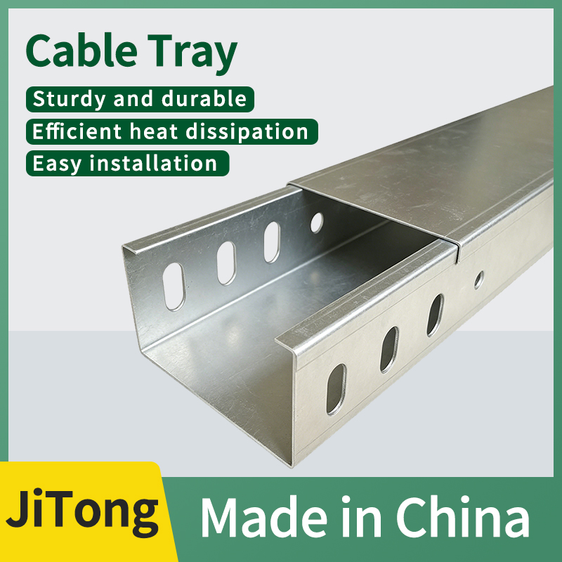
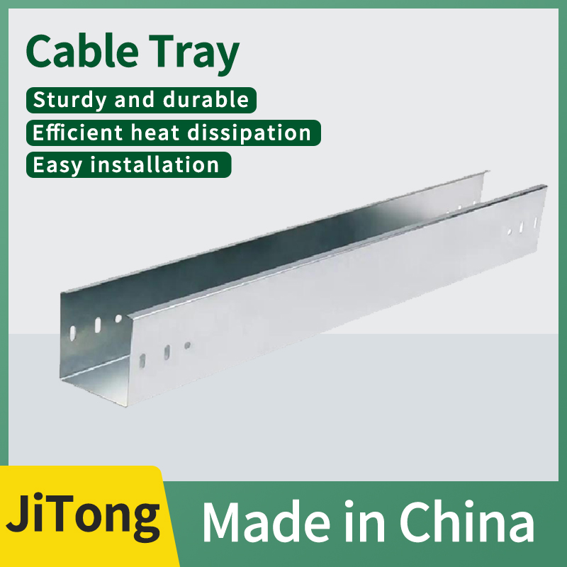
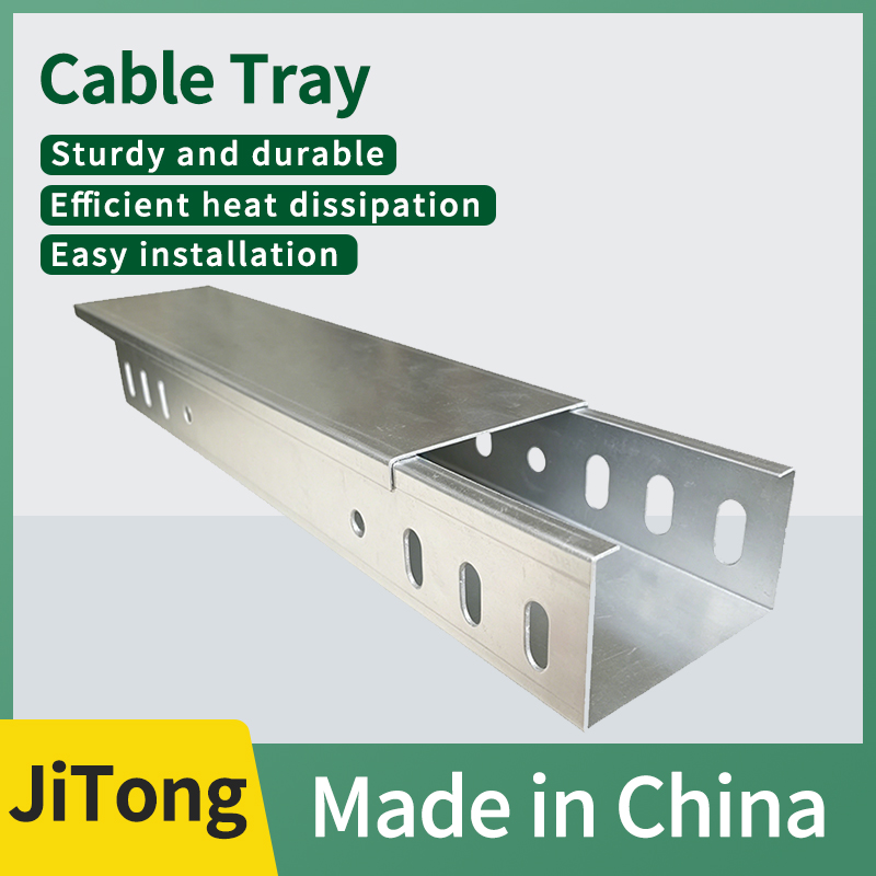
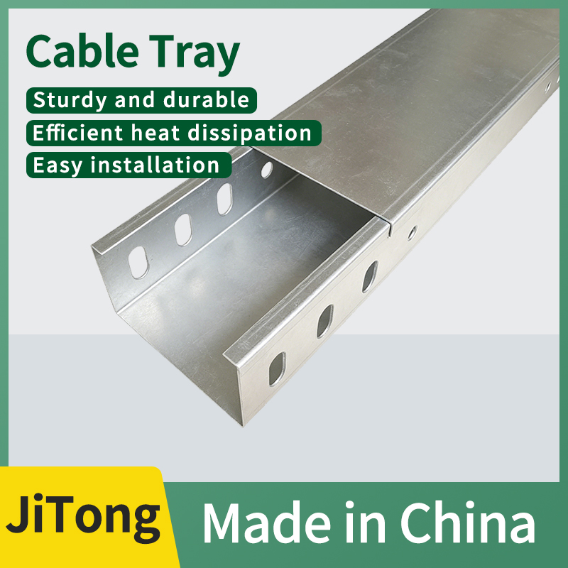
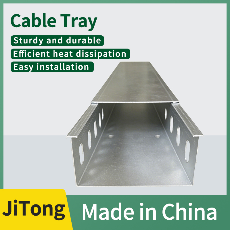
Dimensions (Width × Height, unit: mm):
(1) Height 50 Series: 100×50, 150×50, 200×50, 300×50, 400×50
(2) Height 100 Series: 100×100, 150×100, 200×100, 300×100, 400×100, 500×100, 600×100, 800×100
(3) Height 150 Series: 200×150, 300×150, 400×150, 500×150, 600×150, 800×150, 1000×150
(4) Height 200 Series: 300×200, 400×200, 500×200, 600×200, 800×200, 1000×200, 1200×200
(5) Extra‑long Span / Widened Cable Tray for Power Plant Special Use: 1000×100, 1000×150, 1000×200, 1200×200
Plate Thickness (unit: mm): 1.0/1.2/1.5/2.0/2.5/3.0/3.5
Ⅰ. Product Definition:
Hot-dip galvanized large-span cable trays (standard model DJ type, including DJ-T ladder type, DJ-P tray type, and DJ-C channel type) are made of thickened Q235B high-strength steel plates. They are reinforced with double-layered flanges, bottom reinforcing ribs, and widened and heightened side beams to enhance rigidity. The finished products undergo overall hot-dip galvanizing for corrosion protection. Different from conventional 2m standard trays, the single-section standard length is 6m, and the support span can reach 3 to 12m. No dense support arms are required, specifically addressing the needs for long-distance laying of high-altitude, large-space, and heavy-duty cables. They are the core wiring carriers for large-scale industries, outdoor pipe racks, and substations.
Industry definition standards for conventional ordinary cable trays: single section 2m, recommended support span 1.5-2m; large span cable trays: mainly single section 6m, conventional support span 3m/6m, reinforced type maximum span 9-12m; specifications require full-load deflection ≤ span L/200, safety factor ≥1.5.
II. Production and Hot-Dip Galvanizing Anti-Corrosion Process
1. Enhanced Forming Process: Plate Thickening: Conventional thicknesses are 2.0/2.5/3.0mm, and steel plates of 3.0~4.0mm are used for widths exceeding 800mm. Structural Reinforcement: Double-layer bending and thickening with edge curling for side panels, multiple longitudinal reinforcement ribs stamped on the bottom plate, and densely welded ladder rungs on the ladder frame (with a spacing of 150/200mm). Ultra-Long Integrated Cutting: Single-section 6m full-plate forming to reduce splicing seams; supporting 6m long elbows, tees, reducers, and supporting thickened connecting pieces; all holes are prefabricated for lifting and grounding, eliminating the need for extensive on-site drilling.
2. Hot-dip galvanizing anti-corrosion process (GB/T13912 standard): degreasing and degreasing → acid pickling and rust removal → plating activation → soaking in a zinc bath at 450~480℃ for 3~5min → centrifugal zinc removal → water cooling and passivation. The average thickness of the zinc coating is ≥65μm, with a local minimum of ≥45μm, and the adhesion amount is ≥610g/㎡. The zinc-iron alloy is metallurgically bonded, making it resistant to peeling due to impact. It passes the salt spray test for over 3000 hours, and has a service life of 20~30 years in coastal, chemical, and outdoor environments. On-site cutting and drilling sections must be coated with zinc-rich repair paint for protection.
III. Mainstream Structure Classification 1. DJ-T ladder-type large-span hollow ladder rung structure, with excellent heat dissipation, is suitable for high-voltage, large-section heavy-duty power cables, and is the preferred choice for power plants and pipeline corridors.
2. DJ-P tray-type large-span baseboard with heat dissipation punching holes, the entire baseboard supports cables, allowing for separate laying of strong and weak electricity, taking into account both heat dissipation and protection, and is universally applicable for comprehensive wiring in factories.
3. DJ-C slot-type large-span fully enclosed slot body + matched 6m long galvanized cover plate, with excellent electromagnetic shielding, dustproof and waterproof performance, used for instrument, DCS, and communication weak current backbone.
IV. Core Components
1. Straight Connectors: extended and thickened connecting pieces, hot-dip galvanized high-strength bolts;
2. Special-shaped Components: 6m horizontal bends, vertical up and down bends, tees, crosses, reducers, inner/outer bends;
3. Auxiliary Materials: heightened and thickened support arms, load-bearing columns, metal partition boards, 6m long galvanized cover plates, grounding jumper wires, lock catches;
4. Seismic Components: seismic support hangers (mandatory for factories, tunnels, and substations).
V. Core Advantages
1. Ultra-large support span, significantly reducing the amount of supports. For a conventional 6m span, only two ends need to be supported. Compared to ordinary 2m trays, the amount of support arms and columns is reduced by more than 60%, reducing the cost of support materials, drilling, and lifting labor by more than 30%. In open factory ceilings, areas crossing roads, and areas crossing equipment, there is no need for intermediate columns, which does not obstruct equipment pathways.
2. With ultra-high load-bearing capacity, resistance to bending without deformation, double-layer crimping, and a mechanical structure with multiple reinforcing ribs, the rated uniform load for a 6m span can reach 300-1000kg/m, and the sag under full load is strictly controlled within the specified limits; it can bear multiple high-voltage cables, heavy-duty high-voltage single-core cables, and remains undeflected and undistorted under long-term heavy loads.
3. Hot-dip galvanizing provides long-term corrosion protection, with a thick zinc layer for cathodic protection suitable for both indoor and outdoor use. It is resistant to salt spray, rainwater, acids, alkalis, and moisture, making it suitable for coastal docks, offshore wind power, chemical parks, wastewater treatment plants, and open-air pipe racks. It is resistant to rusting even after long-term outdoor use, eliminating the need for frequent maintenance.
4. Ultra-long single section, high construction efficiency. Each single piece is 6m long and integrally formed, significantly reducing splicing joints, thereby minimizing gap leakage and grounding discontinuities. The speed of high-altitude hoisting and pipeline penetration construction is increased by 50%, shortening the construction period.
5. Adapt to various cabling requirements with ladder, tray, and slot structures to choose from. It can be used for laying high-power power cables and also for enclosed and shielded laying of low-voltage control lines. A single large-span system covers the main strong and weak electrical lines of the entire factory.
6. With strong seismic stability and significantly superior overall rigidity compared to ordinary cable trays, when paired with seismic supports and hangers, it can meet the seismic specifications for substations, tunnels, and industrial plants, avoiding the risk of vibration-induced detachment.
VI. Applicable Scenarios
1. Large steel structure factories and logistics warehouses: The roof is open without columns, with few support points, and the cables are dense and heavy-loaded;
2. Outdoor pipe racks in chemical plants, oil refineries, and wastewater treatment plants, coastal power plants, and offshore wind power platforms (high salt spray corrosion);
3. Urban utility tunnels, tunnels, highway cable trenches, and overhead wiring across roads; 4. Substations, photovoltaic/wind power plant areas, metallurgical blast furnace areas, with a large number of 10kV high-voltage cables laid centrally; 5. Airports, high-speed rail stations, and large venues, with high-altitude long-distance main cables above 8m in height; 6. Equipment-intensive factory areas, with cross-equipment areas where support columns cannot be added in the middle.
VII. Precautions for Construction and Installation 1. All connecting pieces, support arms, and columns must be equipped with thickened hot-dip galvanized components. It is prohibited to mix ordinary thin galvanized accessories to avoid electrochemical corrosion of dissimilar metals; 2. For high-altitude lifting of 6m long trays, synchronous lifting at two points is required to prevent unilateral twisting and deformation; for spans exceeding 6m, intermediate load-bearing columns must be added; 3. Each section of the tray along the entire line should be provided with equipotential bonding to ensure continuous grounding conductivity; for chemical and substation projects, additional repeated grounding should be implemented; 4. When laying strong and weak electrical cables on the same tray/trough with large spans, metal dividers must be installed for isolation; for outdoor and dusty environments, 6m long galvanized cover plates should be provided; 5. For spans of six meters and above, and for heavy-duty cable laying, seismic support hangers should be installed according to specifications; 6. Cut and drilled sections on site should be promptly coated with zinc-rich repair paint to repair damaged zinc layers; 7. After installation, the deflection of the tray should be checked. Under full load conditions, the sag should not exceed 1/200 of the span, and if it exceeds the standard, additional supports should be provided.