Dimensions (Width × Height, unit: mm):
(1) Height 50 Series: 100×50, 150×50, 200×50, 300×50, 400×50
(2) Height 100 Series: 100×100, 150×100, 200×100, 300×100, 400×100, 500×100, 600×100, 800×100
(3) Height 150 Series: 200×150, 300×150, 400×150, 500×150, 600×150, 800×150, 1000×150
(4) Height 200 Series: 300×200, 400×200, 500×200, 600×200, 800×200, 1000×200, 1200×200
(5) Extra‑long Span / Special Widened Cable Tray for Power Plants: 1000×100, 1000×150, 1000×200, 1200×200
Plate Thickness (unit: mm): 1.0/1.2/1.5/2.0/2.5/3.0/3.5
Ⅰ. Product Definition:
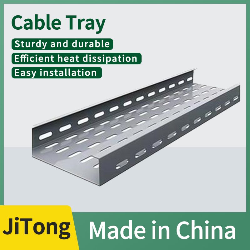
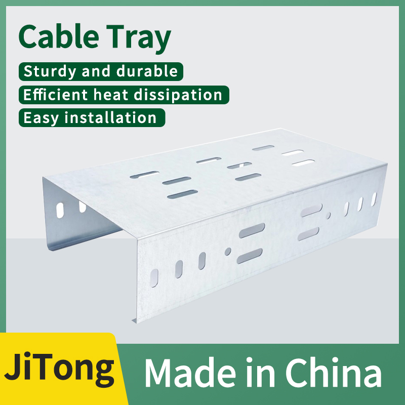
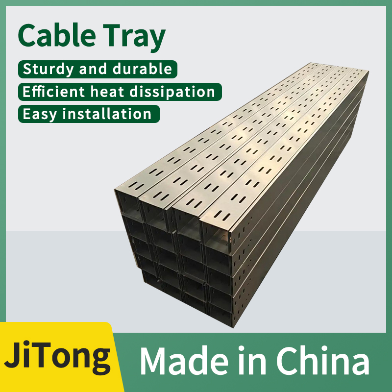
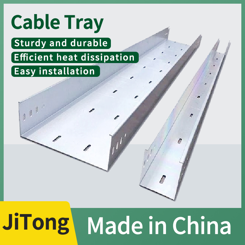
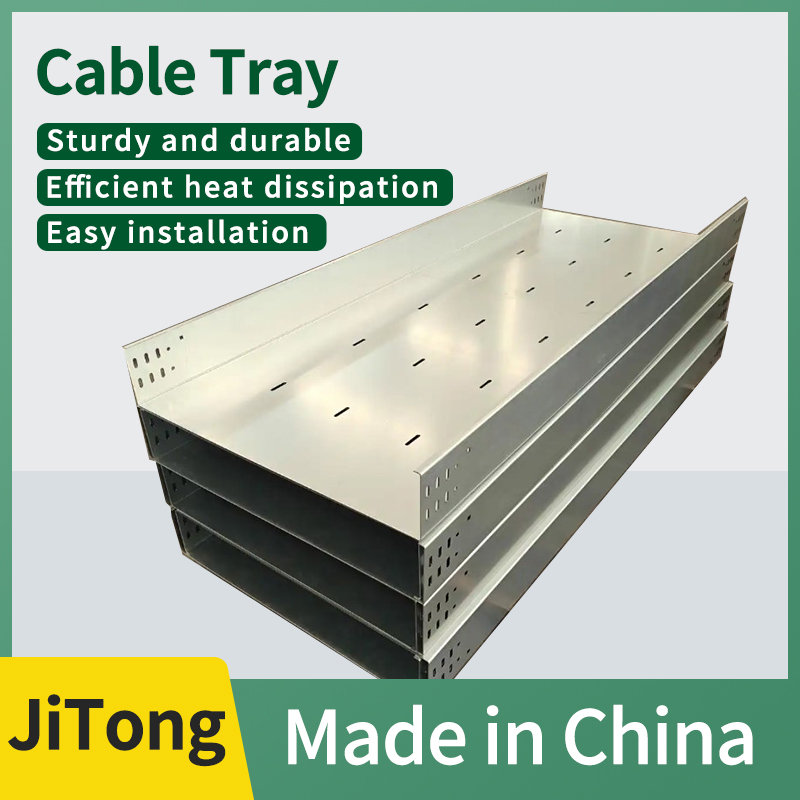
Hot-dip galvanized tray-type cable tray, with base material of Q235 carbon steel plate, integrally bent and formed with punched bottom plate + double-sided high-upright semi-enclosed tray structure. After all components are processed, the entire structure undergoes hot-dip galvanizing for corrosion protection. Its performance falls between fully enclosed trough-type and fully hollow ladder-type, balancing heat dissipation, load-bearing capacity, and basic protection. It is a universal cable tray for both strong and weak electrical wiring. Core structural features include: the bottom plate is covered with regular waist-shaped cooling holes, and the entire bottom plate fully supports the cables, preventing thin wires from sagging and getting stuck; an optional hot-dip galvanized cover plate can be added, significantly enhancing protection and shielding after covering.
II. Production and Hot-Dip Galvanizing Anti-Corrosion Process
1. Tray Forming Process: Steel plate cutting → CNC integrated bending to form side and bottom plates → Stamping of waist-shaped cooling holes on the bottom plate (standard 10×30mm, with a hole opening rate of 30%~50%) → Prefabrication of connection holes and lifting holes; heavy-duty bottom is pressed with longitudinal reinforcement ribs to enhance bending resistance and load-bearing capacity.
Standard thickness of the board: 1.2/1.5/2.0/2.5mm; for widths exceeding 600mm, a thickness of
2.0mm is recommended; standard single-section length is 2000mm, and customization for large spans up to 6000mm is available.
Ⅱ. Hot-dip galvanizing anti-corrosion process (core of heavy corrosion protection):
Degreasing and degreasing → hydrochloric acid pickling and rust removal → plating activation aid → soaking in molten zinc at 450~480℃ for 3~5min → centrifugal zinc removal → water cooling and passivation.
Inspection of coating structure: steel substrate + zinc-iron alloy layer + pure zinc surface layer, with strong metallurgical bonding and adhesion, and not prone to peeling or falling off due to impact; national standard zinc layer indicators: thin plate ≤5mm, average zinc layer thickness ≥65μm, thick plate >5mm≥86μm, zinc layer adhesion ≥610g/㎡;
self-repairing corrosion protection: sacrificial anode cathodic protection, zinc preferentially corrodes and protects steel at damaged areas of the zinc layer, neutral salt spray test for over 3000h; appearance: silver gray matte finish with natural zinc pattern, distinguishing it from the bright mirror surface of electroplated zinc.
III. Complete set of hot-dip galvanized accessories:
1. All accessories are synchronously and integrally hot-dip galvanized to prevent electrochemical corrosion of dissimilar metals;
2. Straight-through accessories: thickened connecting pieces, high-strength hot-dip galvanized bolts, grounding jumper wires;
3. Special-shaped turning pieces: 90° horizontal bends, 45° horizontal bends, vertical up/down bends, tees, crosses, reducers;
4. Functional accessories: split-type galvanized cover plates, metal divider plates, fireproof dividers;
5. Support system: thickened hot-dip galvanized support arms, columns, seismic support and hangers.
IV. Five Core Advantages
1. Balanced Heat Dissipation and Protection The bottom plate is perforated to facilitate air convection, providing superior heat dissipation compared to slot-type trays, reducing cable temperature rise by 3~10℃; the integrated bottom plate and side baffles prevent dust and cable slippage, offering superior protection compared to hollow ladder trays and providing the highest versatility.
2. Excellent load-bearing performance: The complete bottom plate evenly distributes cable loads, coupled with reinforcing ribs, resulting in a uniformly distributed load that is higher than that of ladder racks of the same specification. It can stably support a mixture of thick high-voltage cables, thin control wires, and optical fibers, ensuring that thin wires do not fall through gaps and get stuck.
3. The hot-dip galvanized coating, with its long-lasting heavy-duty protection and thick zinc layer, is resistant to rainwater, high salt spray, mild acids and alkalis, and high humidity. It can be used for long-term applications in coastal factory areas, wastewater treatment plants, chemical workshops, and open-air pipe racks. With a normal service life of 15 to 25 years, it requires minimal maintenance in the later stages.
4. The strong and weak electrical cables are laid together with adaptations, ensuring flexible wiring without adding covers, with a focus on the heat dissipation of power cables. The installation of metal dividers allows for the co-laying of strong and weak electrical cables in the same slot. After adding a galvanized cover, it provides basic electromagnetic shielding, allowing for the laying of instrument and control cables without the need for separate trays, thus saving both cost and installation space.
5. The semi-open structure facilitates maintenance and wiring, allowing for inspection and addition/removal of cables without completely dismantling the cover plate. The holes on the bottom plate can be directly used to tie and secure cables, ensuring neat and orderly wiring. This design reduces labor hours for future expansion and fault maintenance.
Ⅴ. Applicable Scenarios:
1. Areas with mixed strong and weak electrical installations: power distribution rooms in factories, office buildings, commercial complexes, data centers, and underground parking garages with main cables;
2. New energy factories, photovoltaic/wind power plant areas, tunnels, and general industrial workshops (requiring both heat dissipation and protection of fine signal lines);
3. Coastal factory areas, wastewater treatment plants, and light corrosion chemical workshops (requiring outdoor/humid heavy-duty corrosion protection);
4. Central control rooms and computer rooms with comprehensive cabling, where power cables, network cables, fire control lines, and instrument cables are laid simultaneously;
5. Places with a mix of thick and thin cables, a large number of cables, and where both ventilation and heat dissipation are required while preventing fine wires from scattering and getting stuck.
VI. Key Points of Construction and Installation Specifications
1. After on-site cutting and grinding, the metal sections should be immediately coated with zinc-rich repair paint to seal the bare steel and prevent corrosion;
2. Support arms, columns, and connecting bolts should be uniformly equipped with hot-dip galvanized parts, and the mixed use of ordinary electroplated galvanized accessories is prohibited;
3. Each section of the entire cable tray should be equipped with grounding jumper wires to ensure continuous equipotential conduction, and chemical plants and substations should be provided with additional multiple grounding;
4. When laying strong and weak electrical cables on the same tray, metal separators must be installed for complete isolation; in open and dusty environments, galvanized cover plates should be added throughout the process;
5. For heavy-duty trays with a width of over 600mm, support arm reinforcement points should be added to control deflection and deformation under long-term load;
6. For six-meter large-span trays and high-voltage main lines, seismic support hangers should be provided according to specifications.